I see a good amount of intake discussions popping up on forums and wanted to do a small write-up about what to look for when choosing an intake and some turbocharger and airflow theory.
The rule of thumb with intakes is that the larger the diameter, the shorter the intake and the fewer the turns the better in terms of what the turbo “likes” (less losses = more power). Let’s elaborate on this a little bit.
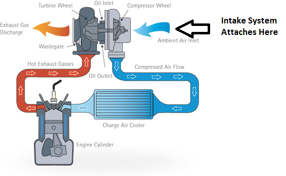
Turbocharger compressors (the silver cold side of the turbo) operate at what is called a pressure ratio. What this means is that the compressor increases the pressure of the air from the Inlet (from intake) to the Outlet (to intercooler) of the compressor when they are spun up by the exhaust gases (spooled up). This gives us BOOST!
Boost gives the engine more airflow than it can draw through itself (essentially increasing the volumetric efficiency) allowing it to make more power. The amount of airflow needed is defined by the size and volumetric efficiency of the engine and the power requirements. We’ll go into more detail on this in another write-up.
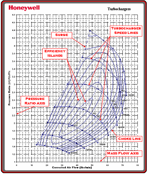
Turbocharger compressor performance is illustrated by a compressor map. A sample compressor map is shown below with the features highlighted. You can read more about compressor maps in this excellent series by Garrett/Honeywell:
Now, the size of the compressor and turbo really depends on application. Generally, we want very little lag and decent top end so the turbo we choose (and the stock one in most cars especially) is driven very hard. In such a case, the lower this compressor pressure ratio, the more efficiently the turbo works and the less “work” the exhaust has to put into the turbine to make it spin.
This reduces pumping losses (increases volumetric efficiency), reduces heat, and allows denser air to reach the motor while increasing the knock threshold. All good things and this applies to ANY turbo unless it is grossly oversized for the engine in which case there are bigger problems to address.
How is this related to intake and boost we measure at the manifold?
You can imagine air follows this path into the motor:
Air Filter → Intake Tubing/MAF Sensor → Compressor Inlet → Compressor Outlet → Hotside Tubing → Intercooler → Cold Side Tubine → Throttle Body → Intake Manifold → Intake Valves/Head → Exhaust Valves/Head → Turbo Turbine → Downpipe → Rest of exhaust.
The image below shows this using an illustration.
The compressor map shows you how much a turbo flows at a given pressure ratio (pressure difference between compressor inlet and outlet) at a standard temperature.
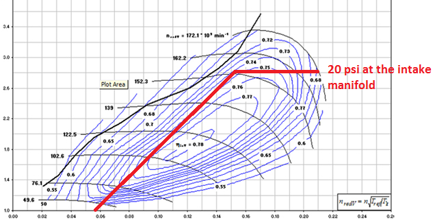
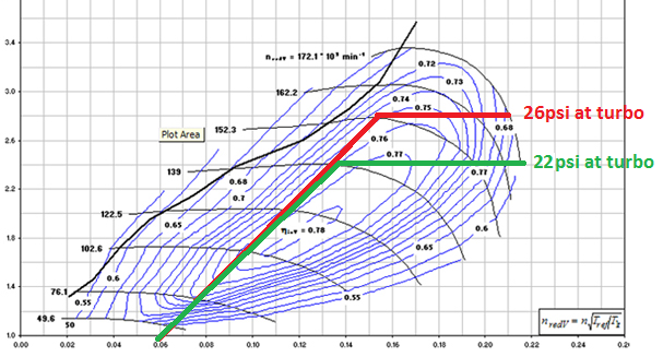
The airflow is on the horizontal (x axis) and the pressure ratio is on the vertical (y axis). As the RPMs increase the motor requires more air to produce more power. For simplicity, let’s say we are running 20 psi of boost at the manifold. You can plot out where the motor operates on the compressor map based on how much air it consumes at that 20 psi with that particular turbo (this case a K03). This looks something like this when the engine is doing a pull in a single gear.
Notice how in this case the pressure ratio that the turbo is operating at is around 2.8 on the vertical axis. At sea level this translates into 26 psi of boost pressure the compressor must generate. But I just said that the car is operating at 20 psi of boost at the manifold right? How can this be?
When you draw air from outside, you are drawing air in at atmospheric pressure. However when it gets pulled through the filter and air tubing, the pressure actually drops BELOW atmospheric. This is due to something called the Bernoulli Principle.
The turbo then pushes air through to the motor but across all the other intake tubing and intercooler you lose more pressure due to the same principle until it reaches the manifold.
When you measure boost at the intake manifold you are measuring it against the atmospheric pressure (called Gauge Pressure) but your compressor is actually operating at a higher pressure ratio/boost level.
Let’s use an example:
– Say the manifold pressure is 20 psi as measured by the ECU or a boost gauge.
– The pressure drop from the intercooler and the piping AFTER the turbo is 4 psi (for example).
– The pressure drop from the intake and filter BEFORE the turbo is another 2 psi (again an example).
That means that the compressor is actually pressurizing air to 26 psi to get you 20 psi of manifold pressure. The more you reduce this pressure drop in front of and after the turbo, the slower you need to spin the turbo, the more efficiency you’ll gain, and in the case of undersized turbos like the OEM, you will gain airflow all while keeping your 20 psi at the manifold.
All this means to you is that your car will be faster! The diagram below shows the same compressor map with the same 20 psi of boost at the manifold (and 26 psi at the turbo in red). Now, let’s assume we run a more efficient intercooler and bigger and more efficient intake and these only drop pressure 1 psi each. This changes the pressure ratio at the turbo to 22 psi to get the same 20 psi at the intake manifold! This is shown in green.
What can we conclude about running a turbo along the green line? Thankfully all good things about both power and reliability.
– Turbo spends more time in the higher efficiency islands.
– The green line extends further meaning that the turbo will flow more air without over-spinning.
– The turbo spins slower, reduces exhaust back-pressure, increases overall engine efficiency
– Turbo runs cooler at lower pressures.
– Engine is less likely to knock.
– Turbo life is extended.
How is this related to the intake?
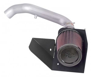
Larger diameter intakes that are shorter, have less turns, and a better flowing filter will really help here. Believe it or not even the filter makes a measurable difference when you’re working with a maxed out turbo like what is installed on most OEM cars and most medium sized turbos. Of course the intake must also fit in the engine bay and also importantly shield the incoming air from heat without being restrictive.
OEM components are sized for the power requirements of the stock car and noise constraints but often do a great job shielding from heat. Compare the sizes, locations, and design of OEM and aftermarket intakes to see this. Some aftermarket intakes are definitely better designed than others.
The intercooler and piping after the turbo have a similar effect and should follow the same low restriction, high efficiency principle. There are a few more details to charge air cooling that will be covered in a different article.
These are some of the things to think about when choosing an intake for the MazdaSpeed, Focus ST, or any other turbocharged car!
Happy Turbocharging!
Alex@Stratified
Image Credits:
http://www.cap-ny153.org/forcesthrust.htm
http://blog.perrinperformance.com/alta-billet-56-turbo-upgrade/
http://http://www.audizine.com


