What wastegate duty cycle and boost curve can tell us about our turbo setups

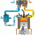
A turbocharger is comprised of a compressor and a turbine linked by a shaft. We won’t go over how a turbo works here but if you’re unsure check out this link put together by Garrett.

Source: Garrett Website

We all want more power and in the case of running a turbo engine, we want to make sure we recognize the bottlenecks of the particular setup we are running so that we can address them without spending money and effort in the wrong areas. Today’s article will focus on what our wastegate duty cycle (WGDC) and boost curves can tell us about our system. First of all, a quick review of how a wastegate works.

In order to generate boost, exhaust gases must pass through the turbine of the turbo located on the exhaust side and spin it. When the turbine has reached the speed necessary to hold the boost that we want, the wastegate opens to divert extra exhaust gases and maintain the turbo speed we want to generate the boost we desire. The turbo speed needed for a particular boost level depends on many variables including engine size, how well the engine breathes, turbo size, engine speed, temperature, etc. The wastegate is controlled by a spring and diaphragm actuator and that spring determines what we call spring boost pressure. Spring pressure is the least amount of boost we can run in the system without going to a softer spring. To increase the boost beyond spring pressure we must either get a different spring (difficult) or we trick the wastegate into seeing LESS pressure at the diaphragm than what the motor is actually seeing. This is done using an electronic solenoid that switches very fast and runs a particular duty cycle.  This is how almost all modern boost control works. The important thing to remember is that 0% wastegate duty cycle (0% WGDC) means the solenoid is not being actuated at all and this results in low boost (spring pressure). When the solenoid is actuated 100% of the time it results in the highest boost the system can run (100% WGDC).

When we want the turbo to spool we run as high WGDC as possible until the turbo spools and then we quickly drop WGDC into a steady state zone without overshooting the boost target. When we want to slow down the turbo we run LESS WGDC and when we want to speed up the turbo we run MORE WGDC.

If you datalog a full single gear sweep and take a look at WGDC and boost for the entire run, you can get some valuable information about your turbo system as a whole.

Below we will examine 3 different setups.

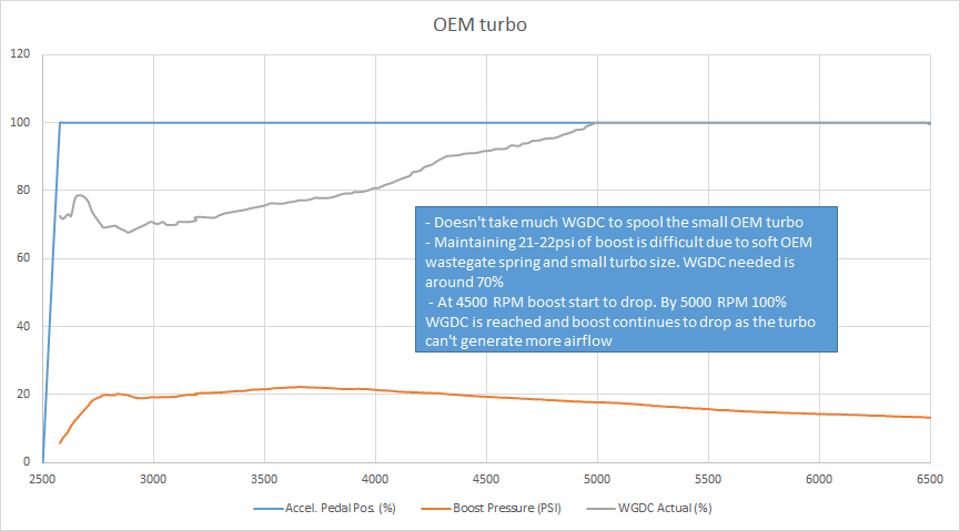
The first is an OEM turbo Focus ST with the OEM wastegate spring (6psi) that is fully bolted. Stock turbos are generally small and therefore you get a quick spool, great midrange, but the turbo can’t keep boost up in the upper engine RPM. As you can see in the graph WGDC is driven to 100% up top and boost still falls off. This means you have peak power and torque early in the rev range but it drops off up top.

Now, the question is what can we do to improve this setup? The car is already fully bolted with well flowing parts such as a catless exhaust, big intake, and good intercooler. Because of this the attention switches to the turbo itself. The OEM spring in the wastegate is only 6psi and we are driving it to over 21psi. This is quite a strain for a 6psi spring and is part of the reason we see such a dramatic boost drop in the upper RPMs when the engine demands more air. While we can replace the spring with a stiffer one to keep boost up, this is NOT a good idea in this case. The turbo is out of efficiency and riding the far right side of the compressor map called the choke line. (Here’s a primer on reading compressor maps). We know this because we know what the stock compressor can flow and we know what the engine is flowing in the upper RPM at that boost level. Adding more bolt-ons to increase flow will have minimal effects on power.

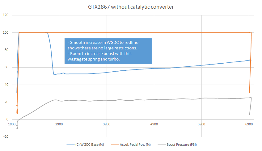
In this case, to improve the top end performance, a larger turbocharger is needed. This trades off the lightning quick response of the OEM turbo for a lot more top end. So now we bolt on a GTX2867 which is an excellent match for the 2.0 Ecoboost. The graph below is a car with full bolt ons, a GTX2867 with a 14psi wastegate spring and high flow catted downpipe. The exhaust is 3″ and it has all the other bolt ons such as an intake and good intercooler.
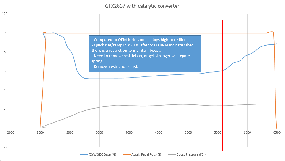
Here things are looking much better. The car is holding 24-25psi to redline, making a lot more power up top and all seems to be well, right? Well, not quite. Again the shape of the wastegate duty cycle (WGDC) shows us that while the system is efficient up to 5500 RPM, there is some sort of restriction beyond that point. The wastegate duty must rise very quickly in order to maintain that boost pressure to redline. Based on the compressor map, we know this turbo is still efficient at this pressure on this engine up to redline. So something else must be causing a restriction. The intake is already free flowing, so we turn our attention to the exhaust side. Here, we have a full 3″ turboback but use a high flow catalytic converter. Controlling boost pressure is very much influenced by exhaust flow and back pressure, so we went ahead and removed the catalytic converter for a race weekend when the car was not driven on the street.

It is now obvious that the the catalytic converter was acting as an exhaust restriction. The WGDC now has a linear rise all the way to redline and we have some headroom should we want to increase the boost further. Of course if we try and push boost and airflow beyond what the GTX2867 can achieve (past 420whp or so) then we will again run into a similar shape and curve to what we saw on the OEM turbo and once again we must look into a larger turbo.

The lesson here is two fold. First, it is important to have a clear goal in mind when building any setup. A big turbo has excellent top end but a smaller turbo has great response and low-end performance.

Secondly, it is important to analyse the data and understand WHICH parts to change to achieve your goals. With the OEM turbo for example a 3″ catback on the Focus ST only yields 5-7whp because it is not a big restriction with the K03 turbo in place. With a GTX2867, a 3″ catback is worth 20-30whp at the 400whp output mark.

The turbo and components should always be matched to the engine, response desired, and overall power and reliability goals. We spend a lot of time analysing data from different setups so if you have a goal in mind and need some information on how to get there, don’t hesitate to get in touch. 

Engineering the right fuel solution … less can be more

In light of recent questions I have been receiving, just wanted to discuss the design choices behind our recently released Xtra fuel system.

First of all, when talking about fuel delivery more is not always better. You want to have as much fuel as you need with a little bit of headroom but you don’t want an under-utilized fuel system. The reason for this is that too much actually hurts driveability and performance.

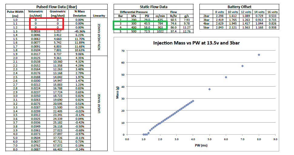
The biggest reason for this is resolution and the fact that injectors are actually mechanical pieces with defined opening and closing times. Injectors are actuated electronically but inside them there are small needles that lift when the ECU turns them on to spray and this is called the injector PW. There is a delay time for them to lift and for fuel flow to stabilize. Usually this delay for port injection injectors is 0.8-1.2 milliseconds (ms). Within this time, the injector is not spraying or the spray is not well atomized. This can cause very uneven delivery from stroke to stroke and air/fuel ratio fluctuations. You can see this kind of phenomenon in older school high horsepower builds where the cars idle very rich and high. These problems are addressed with staged injection system and this is exactly what this Xtra Fuel System is.

Attached is the injector flow data from the injectors used in our kit. I highlighted in red the area where the injectors are opening – you don’t want to operate them in this region! I highlighted in red the flow region in which we are operating at 30psi of boost and 80psi of fuel line pressure.

With the injectors we have chosen the minimum pulsewidth we are running them at is at 1.6ms. The maximum PW we run them at to cover 30% of our total fuelling at 415whp on our shop car is 3ms. This means that any more injectors or any bigger injectors will be difficult to control in terms of pulsewidth eventually not being able to open reliably. Remember that this system has to blend with the OEM DI system in a smooth and predictable manner.

The next question is – are these two injectors big enough for your needs? At 3ms opening time, the two injectors are ran at a whopping 35% duty cycle cycle at 8000 RPM. This is while the aux fuel system covers 125whp worth of fuel. To get to 600whp we need to cover 600-375 = 225whp with the aux system. Let’s take some more stress off the OEM system and we are looking at covering 250whp worth of fuel. At that rate we will need 70% duty cycle from the aux injectors. There is still headroom in the system even at that power level with an 80-90psi rail pressure.

One more thing to keep in mind. Always use as much of the DI system as possible for your power needs. The entire control system in the Focus is built around an efficient DI system so use it to its full potential. This means that the aux system should only be used at WOT and only used as much as there is need. Otherwise, again, driveability, economy, and poor running will result.

These kind of design decisions and A LOT of on-vehicle testing have guided the design of this system and the choice of components used. It’s easy to fall into the trap of “overbuilding.” The best way to maximize performance is building to YOUR power needs. A little headroom is nice. A lot of headroom hurts a lot more and really doesn’t help.

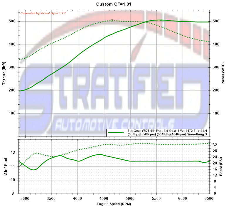
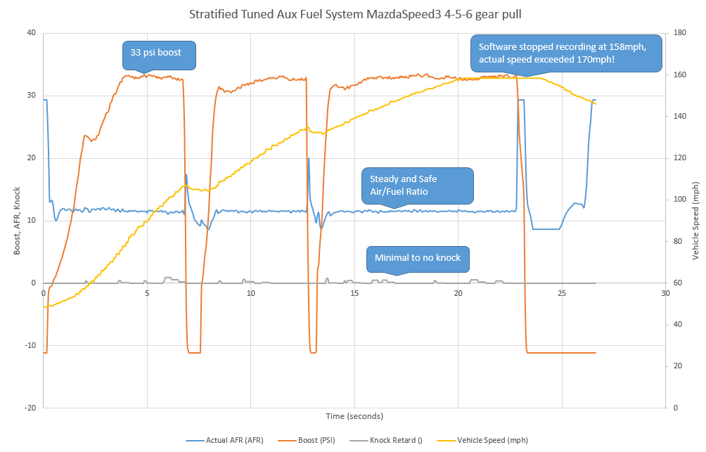
While the big power builds on the Focus are just starting to happen, we have plenty of experience with a similar but slightly older platform and these aux fuel systems. Here’s the result of a two injector throttle body aux injector system we tuned on a MazdaSpeed3 with a GTX3071 turbo making 500whp.

And yes, reliability is there. The proof is in this datalog where the car is driven at WOT to the top of 6th gear (on a closed course)!

If you have questions regarding whether this system is right for your build and power level don’t hesitate to contact one of us on the Stratified team and we are more than willing to answer any questions.

The MazdaSpeed Synapse BPV/BOV

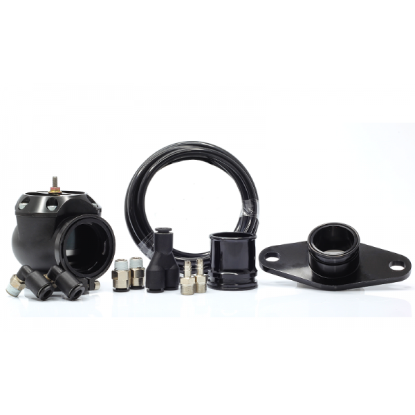
The OEM MazdaSpeed Bypass Valve/BPV  is well suited for up to 18-20psi of boost. Past this point it starts to leak air and torque drops off even if boost is maintained above 20psi. All big turbo cars should upgrade their BPVs. On some cars even the stock K04 turbo is hindered by a leaking OEM valve. The Synapse Valve is the fastest BPV on the market and you can run it as a BOV as well using our Guardian Angel. For this reason we started to carry it right here in our store.
This Synapse valve won’t leak even up to 60psi of boost and the fast response means excellent driveability as well as fast spool and excellent re-spool between shifts. Our BPV of choice for the MazdaSpeed.
If you want more information on why an upgraded BPV is important read our tech article here.

Stratified Tunes Handle Extreme Conditions

We often see the dyno as the best place to test and tune a car – but a lot of the time it doesn’t represent the real world very well. Two areas where dynos fall short is in the cooling department (airflow across the intercooler and radiator can’t be replicated with most fans sitting in front of the car) and in how they load the car. Often the car is loaded too little or too much compared to what it sees on the road.

This can skew the results of the dyno tests and put the car under a lot more stress than you would side on the road.

This gives you a unique opportunity to REALLY see how the tune performs under a fairly extreme stress test. I build adaptive protection into all our Stratified tunes because even though most cars don’t experience what you’re about to see; some do on the track or dyno and the last thing we want is a blown up motor. The behaviour of the tune when stress tested like this is where you really get to see the quality of the tune. And this kind of protection is built into all our tunes, from Flash Tunes to the full custom tunes.

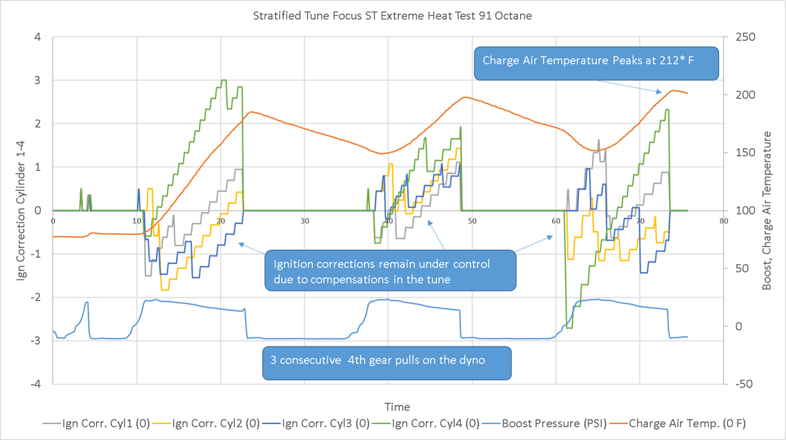
This car has very few modifications and I had no idea how the dyno facility was setup or cooled. Nor did I know that they were going to do 3 4th gear pulls back to back or I would have advised against this kind of torture. However, they did, and the graphs below are the results.

Mods:

2013 Focus ST

Cobb filter in stock intake box
Cobb Downpipe (catted)
Muffler delete
Stratified Tune – In Progress

knock prone 91 octane fuel and no other additives.

As you can see the charge air temperature peaked at 212 degrees! The ignition corrections remained mild from pull to pull and the car STILL made consistent power. Customer drove off the dyno and home with no drama not even knowing the kind of stress test his car just experienced.

Name:  Extreme Test dyno results.pngViews: 4Size:  950.5 KB

Understanding knock and ignition corrections in your Ecoboost powered Ford

All engines knock! Ok, now that that’s out of the way :). Knock or detonation is a phenomenon where the combustion process does not start at the spark plug and propagate completely smoothly pushing the piston down. Instead, there are several small flame fronts that usually appear at the edges of the main flame front during the power stroke. These smaller uncontrolled explosions cause pressure spikes in the combustion chamber. High enough pressure spikes for a long duration can cause damage so naturally we want to avoid high intensity knock in our Ecoboost cars … but not completely eliminate  knock … Let me explain why. Or … just jump to the end of the article for a quick list of what to look for.

ford-ecoboost-2-3-knock-detection

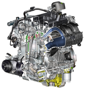
Modern cars such as the one above have well tuned “microphones” called knock sensors that pick up on these sounds and react very quickly to stop detonation when it starts. The 4 cylinder Ecoboost has two of these little guys:

When the ECU detects knock it reduces ignition timing advance. Back in the day when the knock sensor technology was not advanced engines knocked all day long without immediately blowing up. You could hear them pinging going up hills. These days, we push small engines to make a lot more power and we realize that maximum power is made right at the knock threshold. Another way to say it is that we want to keep the engine RIGHT at the edge of knock and the modern ECU in the Ecoboost does exactly this through some smart programming.

The ECU always listens to the knock sensors and knows which cylinder is knocking while it keeps adding timing. Once it starts to hear knock it reduces ignition timing on a cylinder by cylinder basis and eventually it learns an ignition trim that scales the entire ignition table up or down depending on how much knock it picks up. This trim is called the OAR – the Octane Adjust Ratio. Over time, the closer this value is to -1, the more timing the ECU is adding to the base timing table since the fuel is good and it is not picking up much knock. The closer it is to +1, the more knock the ECU is picking up meaning either the octane you are using is poor or the tune is too aggressive or both. So having a peek at your OAR using a logging tool such as the COBB AccessPort ever so often will give you an idea of the fuel quality and how the tune is behaving. ***Keep in mind that the tuner has the ability to adjust how the OAR parameter learns so in some cars OAR will sit at one value and in others it will move around more. If you have concerns, bring it to their attention.***

Using a logging tool such as the COBB AccessPort during a wide open throttle (WOT) run can give you further insight. After datalogging such a run you can look at two parameters to get a good idea of how the tune and fuel are performing. These parameters are knock count for each cylinder (how many times the particular cylinder knocked) and knock intensity for each cylinder (how much timing was pulled during each count – called Ign Corr.) When ignition correction is adding timing, that means no knock is heard by the ECU. When it is pulling it back in a step down fashion, it has done so because it heard knock in that one cylinder.

Keep in mind that the way the ECU reacts to knock is tunable. Some tuners will have the ECU pull a good amount of timing when the severity is higher while others are more aggressive. We like to stop knock the first time we hear it so in Stratified tunes the ignition corrections are larger so that knock does not continue happening in that cylinder.

This is something to discuss with your particular tuner. Once you get familiar with what you’re seeing in datalogs you will know what is and isn’t normal. It is also important to choose a tuner that is experienced with the ECU and how it adjusts timing to get the most from this feature without risking the safety of the motor.

In terms of knock counts – remember that when it’s not knocking the ECU is adding timing until it knocks or until it reaches a ceiling for amount of timing added. Because of this, you are likely to get some knock counts during a pull if the tune is built to maximize performance.

Ideally the tune is setup such that knock event intensity is low and that the tune adds timing in a way that doesn’t cause a lot of sudden knock. It’s normal to see the ECU add a little timing and take some away. What you don’t want to see is very large, multiple, and continuous negative ignition corrections.

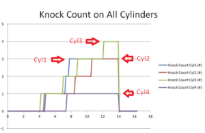
Let me give you an example. Below are the knock counts on a 4th gear pull for cylinders 1-4. This tells you that some knock has happened during the pull but it doesn’t tell you anything about how severe/intense it was. This is incomplete information. You can see here that Cyl1 knocked 3 times, Cyl2 knocked 3 times, Cyl3 knocked 4 times, and Cyl 4 knocked only once. ecoboost-knock-counts-explained-stratified

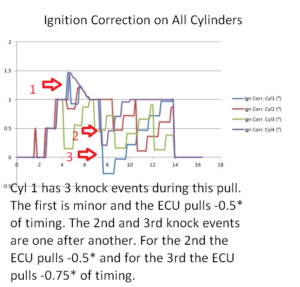
To complete the information here are the cylinder ignition corrections for the same pull. As you can see below Cylinder 1 has 3 knock events labelled on the image. The most severe correction was around -1.0 degrees of timing on cylinder 1 and right away that cylinder added more timing and didn’t knock again. You can also see that each cylinder walks ignition up a little, then steps down when it reaches knock. Finally, you can see all the cylinders are well balanced. There isn’t one cylinder that is significantly better or worse than another one. The tune on this car is running well and it is fine tuned for the vehicle’s modifications and fuel.

ecoboost-ignition-correction-explained-stratified

Also note that there will be differences from pull to pull and this is again normal. Always take a couple of pulls to make sure the data is consistent.

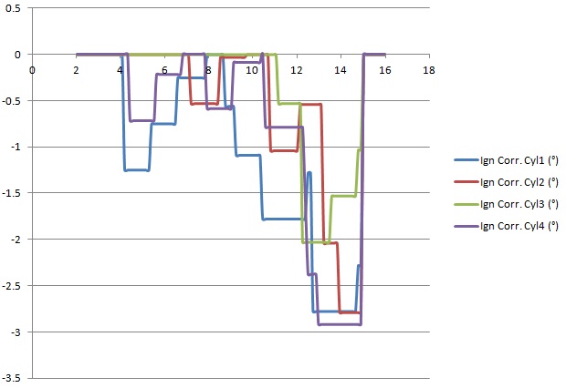
Here is a tune that needs attention or the car is using poor quality fuel. You can see that all the cylinders move into the negative ignition correction zone and some with larger steps meaning that the ECU is picking up knock and lowering timing. Also notice that the ECU pulls timing to avoid knock (a step drop in correction); but the engine knocks again (several more steps down). You can also see that they are not recovering like the graph above (not many steps upwards)

Focus ST ecoboost too much knock ignition correction

Here’s a summary on what to keep an eye on. Keep in mind that looking at min/max ign corr. values does not tell you the whole story. Looking at a datalog of a full RPM sweep and looking at knock counts together with the ign corr value. tells you the information you need:

  • Do ignition drops happen regularly at the same RPM and is it consistent at that RPM and boost?
  • The car ADDS timing unless it hears knock. When knocks is heard you will see a DROP in ignition correction. This drop can make ignition correction negative or it can stay positive depending on what the starting value is. If ign corr. is at +3 and there is knock event, it can drop to +1 for example. If it is at 0, it can drop to -2. The knock that it heard is actually the same, the size of the drop tells you how intense the knock event was. The larger the drop, the more intense the knock.
  • Every time you see a drop, it means knock was detected and the ECU dropped timing to protect the engine.
  • Stratified tunes tend to drop ignition timing quite a bit when knock is detected the first time. This is to prevent further knock in the pull and to keep the engine safer. Always look for the NUMBER of drops, (knock counts) not just the Ign Corr. Value.
  • Multiple drops in ignition correction at the same RPM and across multiple cylinders likely mean that you may need the tune touched up or need to use better quality fuel. We can do this remotely for you using your datalogs.

This car does not instantly blow up when it experiences some knock. Far from it. However if you see consistent knock, either higher octane fuel is needed or the tune should be adjusted.

Happy Tuning,

The Stratified Team