Some things to consider when upgrading your Focus RS’ turbo and shooting for higher power numbers:
The OEM turbo will sit between 350-375whp (to the wheels) on most cars with high quality 93 octane pump gas.
The OEM turbo when paired with E30 fueling or WMI will allow up to low 400whp level.
At the 400-410whp level the OEM fuel system starts to reached its maximum flow capacity and an upgrade is recommended.
With a larger turbo such as the NX2 on a stock motor, you will reach around 380-400whp on pump gas before reaching the knock limit.
Adding ethanol will allow significantly more power on this turbo but you will need additional fuel system upgrades such as aux fuel to support this.
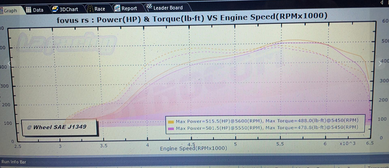
Once you have addressed the turbo and fueling then you can push power on the stock motor beyond 500whp with something like an NX2 turbo.
Keeping power levels in the 425-450whp will extend the life of an OEM motor. You can achieve more power but the more torque the rods experience the fewer cycles they will last.
At power levels exceeding 450whp supporting modifications on top of the usual flow bolt-ons (intercooler, exhaust, intake) will be needed such as a clutch and a 3.5 or 4 bar TIP sensor.
Keep in mind that larger turbos do have a bit of a spool penalty with the NX2 spooling a couple hundred RPM later.
Considering the overall performance per dollar equation, the stock turbo with something like E30 or WMI tuned correctly is a great stock motor option. The NX2 or other turbo upgrades (there are higher performing, pricier options as well) make sense when you can run that high octane fuel AND have a fuel system upgrade.
For more power on pump gas than around 400whp, a better flowing motor is needed and that means cams. We were able to achieve 500whp on pump gas on a built motor with an externally gated 3076 turbo with upgraded cams.
Once the motor is built and fuel system upgraded you can of course push higher with higher octane fuels.
A final note – consider the use of the car. If you want a fun street machine you can pile on the power with just the aforementioned upgrades. However if you want the RS to last on a road course with significantly higher power levels you will want to address engine cooling, the RDU, brakes, suspension and of course tires. So build for your purpose and enjoy the journey!
I want to shed some light on the Ecoboost 2.0 piston failures (the most common failure mode) and offer some pointers on keeping the OEM motor happy and living.
Let’s get one thing out of the way first – the weak point in the EB 2.0 is clearly the piston. Failures happen on stock engines, tuned engines – even ones tuned by Ford Performance! We don’t see failures like this in the 1.6 and 2.3 engines and Ford has made a point of reinforcing ringlands on the 2.3 EB. The 2.3 is more likely to toss a rod before a piston falls apart. Every engine has a weak point.
Now that this is out of the way – let’s look at what makes the engines fail and how to make it less likely for it to happen to your Ecoboost!
Fuel and Air Fuel Ratios
The car uses full time closed loop fuel control using a wideband O2 sensor. That means it is always adjusting the air fuel ratios (part throttle and wide open) to match what is being commanded in the tune. Using a speed density strategy (using pressure sensors to infer air mass consumed by the engine) makes the air fuel ratios unaffected by charge air leaks that would throw MAF based cars off. Having looked at 10s of thousands of datalogs from these vehicles, we almost never see them deviate from target air fuel ratios. The only exception is if there is an exhaust leak that draws oxygen into the exhaust stream “fooling” the wideband sensor. If severe enough this will trigger a “lean” running CEL. Check and fix exhaust leaks (and boost leaks for the sake of performance).
Carbon buildup often interfere with injector spray patterns. Cars driven in traffic and idled for long periods of time are more prone to this. Consider an injector cleaning or replacement as the engine gets up in age past 60,000 miles.
Boost
In terms of boost pressure – the OEM turbochargers have a very weak wastegate spring with a large internal wastegate. This in turn means that boost will taper regardless of what you do electronically with the OEM wastegate actuator. This prevents overspeeding of the turbo and boost is held at peak values for a very short section of the power band (tapering starts just past 4000 RPM and tapers to 13-16psi by redline). The OEM intercooler is not designed for performance and extended high gear, high load conditions will warrant an intercooler upgrade. Changing your wastegate actuator or turbo definitely requires a retune so don’t make these changes without having tuning handled as well.
Spark and Knock
“Normal spark knock” is very well handled with the OEM knock control system. You never see pistons pitted from detonation when taking the engines apart as the ECU if setup correctly is very fast to react and again if setup correctly effective at adjusting for variance in driving conditions and octane levels. The most common spark related issues are spark plugs. Consider them a maintenance item and replace spark plugs every 20,000 miles on a tuned engine. Replace them with a step colder plug gapped at 0.026″. Failing to do so will cause misfires which add to carbon deposits.
If you got this far excellent; I am going to get into the issues that cause these cars to fail as we observed from working with them over the years.
Common Failure Modes and Avoiding Failure
1. LSPI – low speed pre-ignition. The common killer of downsized highly boosted direct injection engines. A concoction of oil blowby, carbon buildup, high torque, oil formulation, injection spray pattern will cause the mixture to pre-ignite and be immediately followed by what is known as super knock. That means that the mixture will ignite well before the spark plug is triggered by the ECU. The chain of events that follow will quickly destroy a piston as the expanding hot combustion event will push down on an upward moving piston. It only has to happen a few times. The most common time this will happen is when you have been cruising on the highway and then punch the throttle or get into boost quickly. Remember the car will build a lot of boost even at part throttle.
The hot engine in combination with a lot of PCV oil flow make the scenario much more likely. This is the reason you often don’t see these engines failing at wide open throttle. During an LSPI event you can get an outright failure or you get a crack that will eventually lead to the failure at what appear odd times. There are many ways to mitigate LSPI but the fundamental reason for it is ingrained in the design of the motor. Things like water-methanol injection, added port injection, carbon cleaning, using high quality oil and changing it often (there are now oil formulations designed to be more pre-ignition resistant) and good intercooling go a long way. This first part comes down to keeping the engine cleaner and cooler.
This engine when tuned will makes the majority of its torque in the lower range of the power band with an OEM turbo. That’s simply a physical fact from the way the engine and turbocharger are designed. This is the operating zone associated with LSPI. Keep this in mind and AVOID getting into boost right away after you have cruised on the highway for some time. Downshift, ease into boost, build it gradually and then get into it. After this initial time easing into it, have a blast going through the gears! I also recommend to avoid loading up the motor in the low RPM range and a high gear in general – downshift if you are under 3000 RPM on the highway and you need to make a pass.
Don’t confuse this with not driving the car hard. Cars that survive the longest are often well exercised. Run it through the gears in boost and allow some of the oil and carbon residues to burn up.
2. Another scenario that is hard on the rotating assembly – rods and pistons – is sitting on a rev limiter. Launch Control, Redline Rev Limiter, Flat Foot Shift Limiter all work the same way. The OEM logic for this cycles cylinders on and off to maintain a certain engine speed by shutting off fuel and ignition temporarily on some cylinders. However the acceleration and deceleration of the rotating assembly is hard on the components. This often triggers the knock sensors also indicating the resonance created by this activity (slap and lash) is similar to detonation events and unhealthy for the motor.
Sitting on limiters excessively for public displays is not doing the motor any favors. We offer crackles which are NOT achieved by adding any fuel or energy to the engine. We are careful to implement these in an OEM-like fashion (common in other makes like VW, Porsche, even the Focus RS). Let me be clear, the crackles are NOT an invitation to be abusive to the motor if you want it to last. So, sorry for all those who ask but we don’t and won’t purposefully make the cars shoot flames.
The engines are not inherently weak and we have customers with hundreds of track lapping days on OEM motors making 350-400whp on larger turbochargers. The motors survive. I recommend reading some of the tech literature we have on our site meant to help you, the enthusiast. With an Accessport in your hand you can view and datalog a lot of tuning parameters for yourself including air fuel ratios, boost, knock, charge air temperatures and those articles teach you how to interpret most of these. If you have questions or want us to perform datalog reviews get in touch – we offer these for every car we tune!
Enjoy the cars, tune them well, operate them wisely, and be familiar with these excellent machines, their weak and strong points.
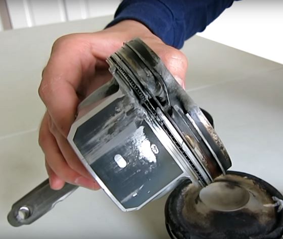
With our RS coming up on 10000 miles and a year of development and (hard) driving, we thought it would be a good idea to borescope the cylinders and see how things look. This is a 2016 September build and the car has definitely been put through its paces on both the track and street.
The good news is that things look great! Spark plugs show the correct heat range (we run a step colder) and even burning across all the plugs.
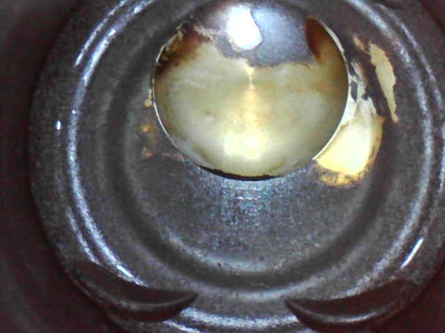
Digging deeper into each cylinder we see that the pistons have the usual carbon buildup. We also see how effective the bowl design is at directing fuel and preventing it from being projected on the cylinder wall. You can see in the image below that the fuel spray is well contained within the center bowl (and this cleans it of carbon buildup). Keeping fuel off the cylinder walls prevents them from being washed down and oil dilution.
Below is a video of one of the bores. The cylinder head gasket is the line in the center of the image. We checked all cylinders and none showed any signs of deterioration at this level. The black staining you see on the piston deck is from carbon deposits and the piston rings not coming up high enough to scrape it off the cylinder wall. This is normal.
Here’s to 10000 more! We will keep you all posted. CheeRS!
A lot has been made of the Focus RS Ecoboost 2.3 head gasket failures. It seems to be an issue that has occurred in both modified and unmodified vehicles. I am not certain what percentage of vehicles are affected. However we have spent significant time looking at the mechanics of the failure and wanted to share this with our customers and community.
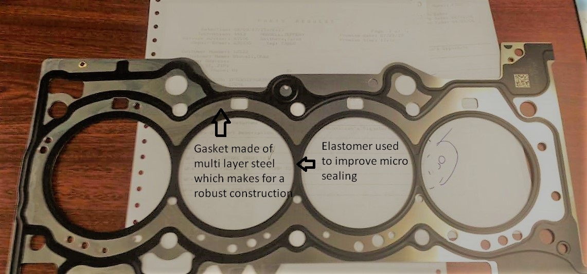
The Focus RS uses a multi layer steel (MLS) head gasket. This is a very capable method for sealing the block to head interface. This multilayer gasket is enhanced by an elastomer that further helps seal critical areas.
The Focus RS 2.3 Ecoboost engine block is an open deck design. This means that the cylinders are not attached to the outside of the block structure at the sealing surface of the head gasket. This space is filled with engine coolant.
The head and block are secured to each other using torque to yield bolts (which do not require re-torquing the head fasteners after the engine is heat cycled). In spite of this there is inevitable movement between the two sealing surfaces. The two types of movement are vertical movement (which is what causes head lift and a sudden gasket failure) as well as lateral movement. This lateral movement is of most interest in this situation. Minute lateral movement causes what is called gasket fretting/scrubbing. There are two mechanisms that cause this lateral movement:
Thermal deformation. As the engine is brought through a range of temperatures (within normal operation), the expansion and contraction of the head and block cause this lateral movement between the two interfaces. The movement caused by this is however low cycle, as the engine is warmed up and cooled down relatively few times compared to the next mechanism.
The most relevant mechanism for lateral movement is due to cylinder firing. When a cylinder fires, it applies pressure on the open deck cylinder structure. This in turn causes this minute movement between the two interfaces scrubbing them at a high rate.
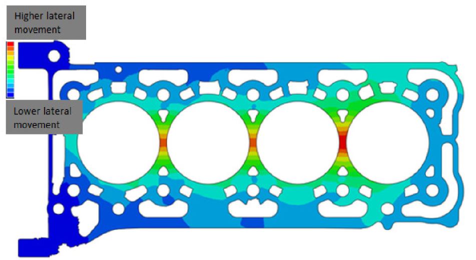
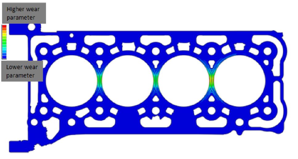
The result of this scrubbing is material loss from the head gasket, block, or head. Over time, the seal between the block and head can fail. The area where it will fail first is the area with: the highest movement, the highest contact pressure, and the least sealing material available.
The area of highest lateral movement for the Focus RS is between the cylinders.
The area of highest contact pressure is around the cylinders (because this is where the combustion pressure is highest and needs the best seal). This is by design.
The area that will inevitably experience the highest wear rate will be between the cylinders. Manufacturing discrepancies, vehicle use, temperature fluctuations and other factors will influence whether a failure will occur on a vehicle and if so when.
There are two methods to reduce this scrubbing wear. One is to stiffen the block structure. When rebuilding an engine for example, using the closed deck 2.0 Ecoboost block is an attractive option. However, Ford could not use this block in production and I am certain there are good reasons for this; likely related to emissions certification.
The second method, and what is being implemented as a fix is to redesign the head gasket.
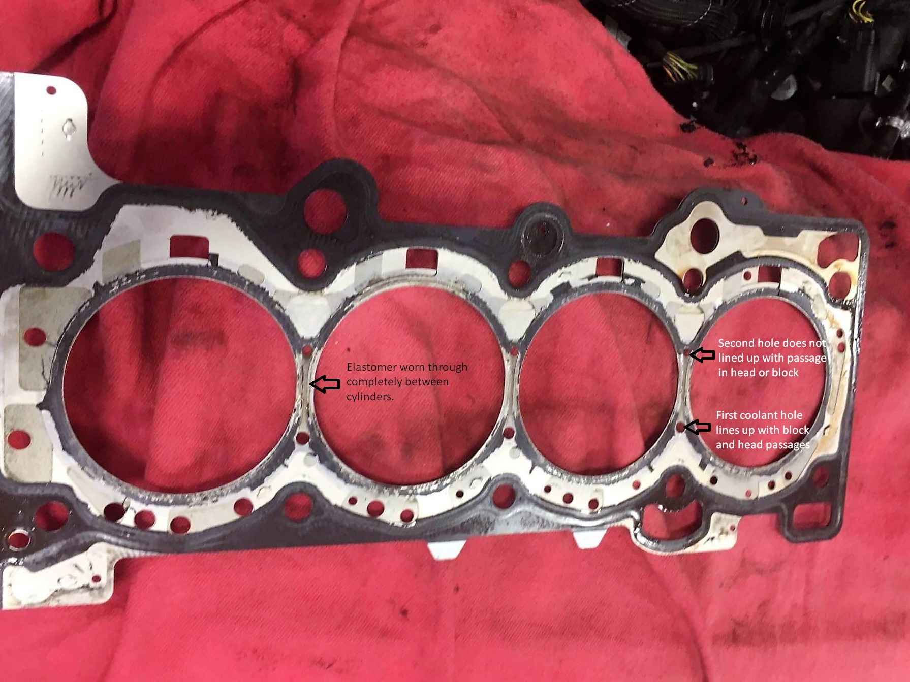
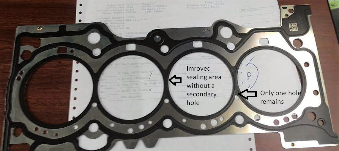
Below is an image of a failed Focus RS gasket. A few things to note:
There is a very high wear rate of the elastomer (black section) between the cylinders. This is where the gasket has failed. You can see that it is almost completely missing in these areas.
Notice how thin the sealing area is between the cylinder overall.
Looking carefully you will notice that the are two holes in gasket between the cylinders marked on the image below.
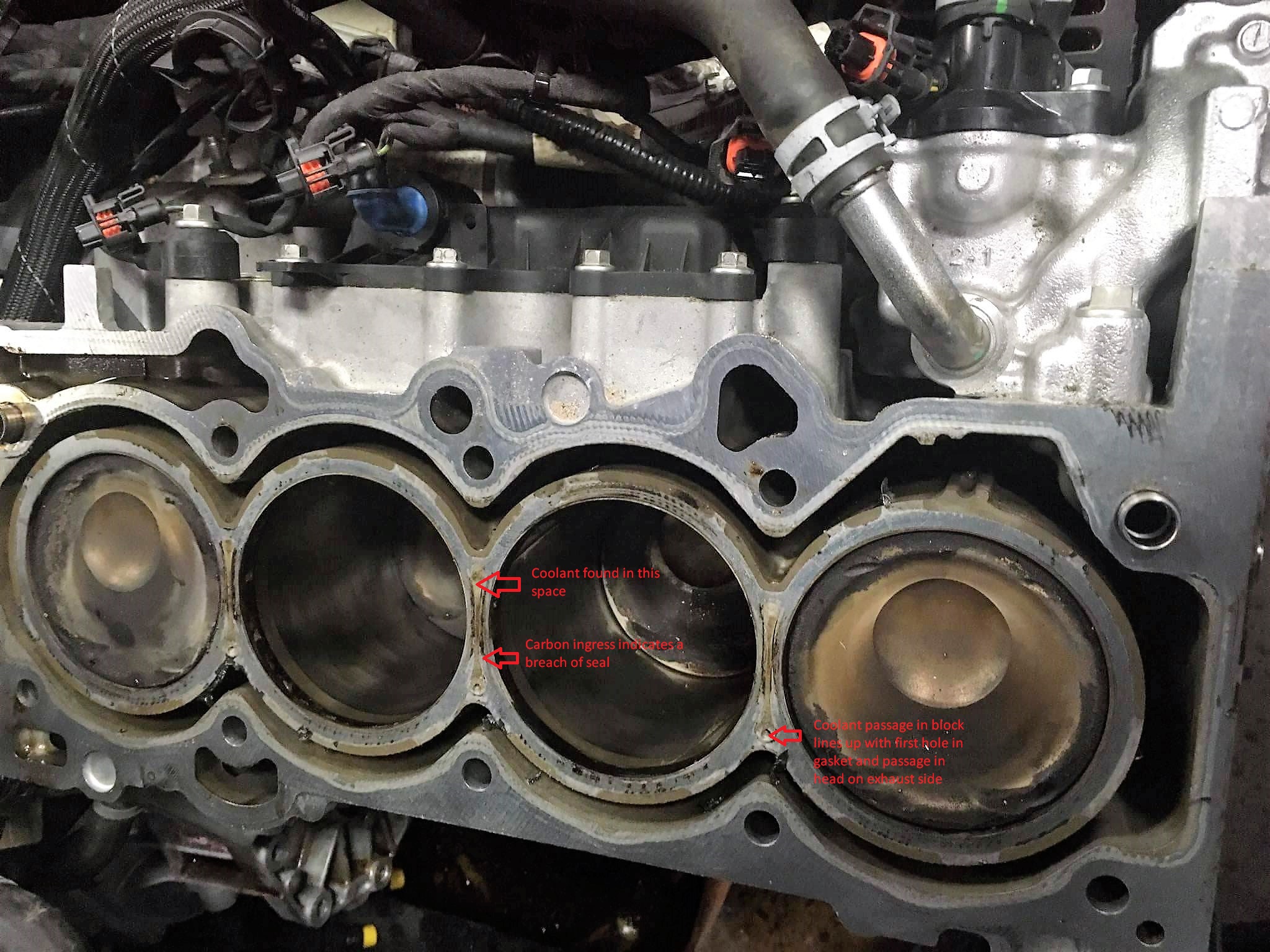
Now let’s have a look at the block. You can see there is a very smallcoolant hole on the exhaust side. This hole lines up with one of the holes in the failed head gasket. You can also see a trail of coolant marking on the block surface leading to the second hole. This shows there is no elastomer between the cylinders on the original head gasket.
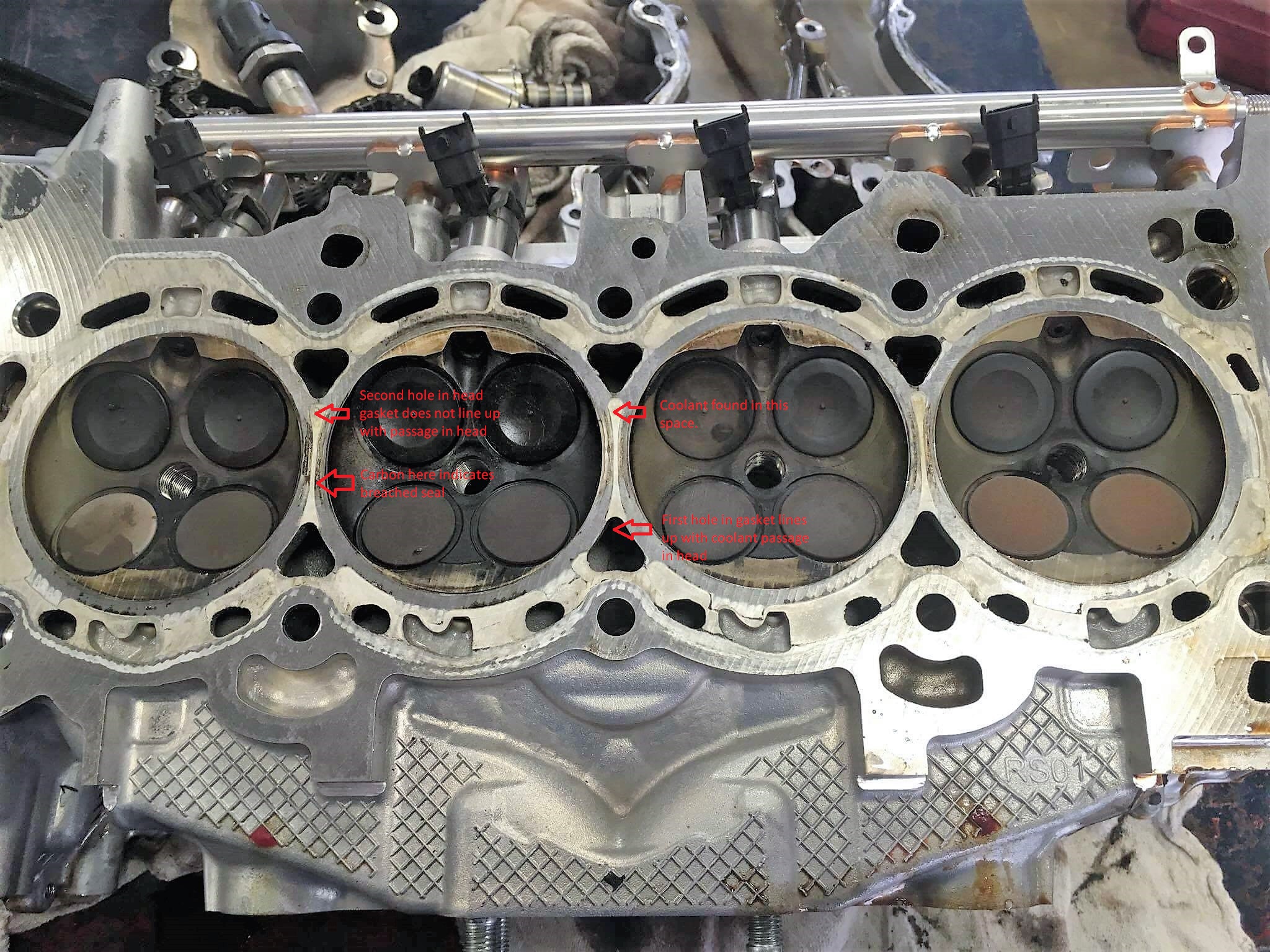
Looking at the head, you can see that the first hole on the head gasket lines up with a coolant passage. The second hole, however does not line up with any coolant passage. Once again, the head shows that coolant was found in the area between the cylinders but this was a closed path. Overall the cylinder sealing area was very narrow and the head gasket failed after a number of miles.
When the car was brought to the dealer, it was repaired with the head gasket shown below. There are some very important changes in the area between the two cylinders on the updated gasket.
The second deadheaded hole is no longer present
The entire area between the cylinders is now coated in elastomer. This will increase the sealing surface area and better distribute the clamping force in this critical area. This will in turn reduce the fretting/scrubbing failure of the head gasket.
The latest gasket part number is G1FZ-6051-C and this is what dealers are replacing failed gaskets with on vehicles that experience this failure. I am not sure at what point the factory engines have received this latest gasket part number. The only indication I was given was that this part number was available to service centers sometime between 3/27/17 and 8/10/17. Again, this says nothing regarding when this change was made to vehicles coming out of the factory.
I hope this clears up some of the confusion around these head gasket failures and what is causing them. The symptoms of failure are:
Loss of coolant.
Misfires, especially on a cold start and rough running.
Coolant fouled/wet spark plugs.
If you experience these symptoms, take the car in to Ford for the fix. Otherwise, enjoy the RS! It is not the only car in history to experience difficulties with head to block sealing. High output, low emissions, small displacement engines like the RS are a challenge to engineer and can have some teething issues; but at the same time we can all agree that fun behind the wheel was certainly well engineered!
The Stratified Team
Photo credit:
Brewer, T. and Chen, X., “Cylinder Head Gasket Fretting/Scrub Mechanism Investigation and Analysis Procedure
Developments,” SAE Technical Paper 2017-01-1091, 2017, doi:10.4271/2017-01-1091.
The Ford Ecoboost knock detection system is one of the more complex systems out there. A lot of the vehicles using the Ecoboost engine are rated to use fuel that ranges in octane from 87 to 93 octane. Because of this, Ford built a system that is very powerful and adaptive. It actually learns your fuel quality while you drive. All the EB engines we work with use this adaptive timing system. This is great for us calibrators as we can build failsafes and adaptability into the tunes – but it has to be setup correctly.
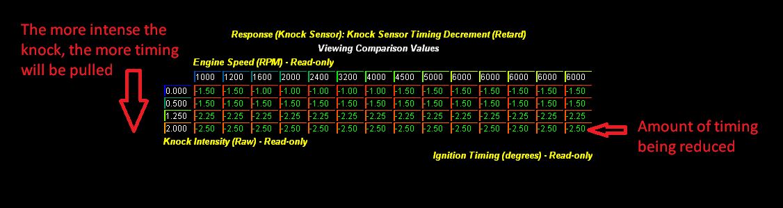
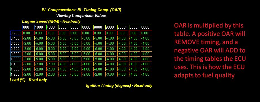
The knock detection system starts with the sensors (microphones) that pick up engine noise and are mounted to the engine block. If the engine noise falls within the correct frequency and window of operation (around the time the spark plug fires), the ECU registers this as knock. When knock is registered, the ECU looks at the Knock Response table pictured below. Based on the intensity of the knock it subtracts timing advance from the Ign. Corr. Cyl X Parameter (which you can view and datalog) on a per cylinder basis. On each knock events it also increments the Knock Count Cyl X parameter which can also be viewed. Both of these parameters are reset to 0 once you let off the throttle, shift gears, or experience a throttle closure.
Keep in mind that the following ECU tables shown have OEM values. We adjust these to better suit our performance criteria, but the principles remain the same.
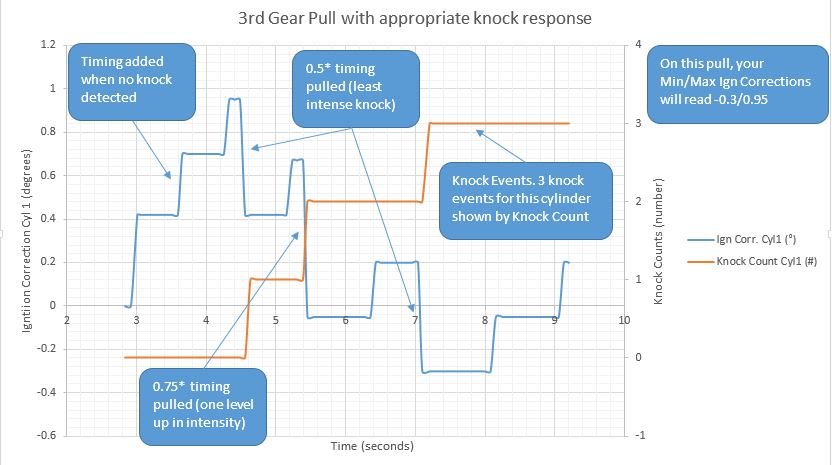
The amount of timing being pulled for each knock intensity and engine speed is completely under the control of the tuner who builds the tune. You want to make sure that you pull enough timing per knock event to maintain engine safety and stop the knocking. Here’s how this looks in a graphed datalog of a single cylinder during a pull.
These negative ignition values are always subtracted from the current Ign Corr. Cyl X variable for each cylinder. This is important to understand because the Ign Corr. Cyl X variable also ADDS timing when the system does not “hear” any knock and you are on the throttle.
The rate at which timing is added and how much total timing is being added is also adjustable in the tune. Ideally the tune should walk timing up at a reasonable rate that is not so fast such that knock is induced and not too slow such that performance is left on the table.
One thing that has to be understood is that all engines will knock at some point regardless of tune and fuel used. The combustion process is a chaotic process and sometimes you get some irregularities. This is inevitable. You want to tune out heavy and sustained knocking, but completely eliminating all knock is not something that is realistic – especially in a street engine. Handling knock correctly is the key. Light knock will NOT damage an engine especially if timing is reduced via a reduction in Ignition Corrections when it happens. LSPI (Super Knock) and bouncing off a Rev Limiter have a MUCH more damaging effect on the pistons and rods.
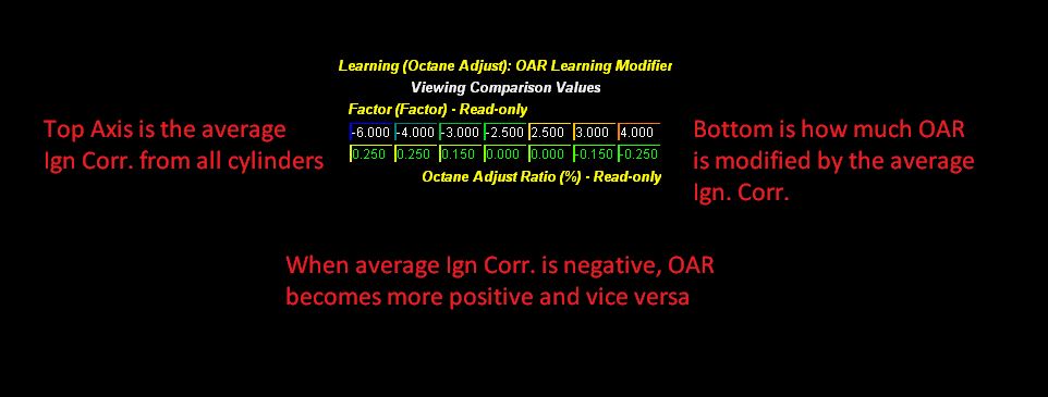
The beauty behind this knock control system that both adds and subtracts timing is that it also LEARNS the quality of your fuel over time. The learning variable is called OAR (Octane Adjust Ratio). This variable is like a fuel trim but used for ignition and load/boost targets. It can range from -1 to 1. Below is the table that allows the ECU to learn and adjust OAR. You can see from this table that in order for this system to work, ignition timing and the Knock Response table must be set such that the ECU can ADD and SUBTRACT enough timing to make the Ign. Corr. Cyl X parameterspositive as well as negative during a pull. With an adaptable tune you are likely to see Ign. Correction numbers that are both positive and negative at times.
Finally, this OAR number is not just another pretty face. It affects the timing AND load/boost tables the car will be targeting. An OAR that is closer to 1 will remove both timing and boost reducing future knocking. An OAR closer to -1 will add timing and boost due to good quality fuel and increase performance. It is normal for OAR to fluctuate slightly depending on your fuel quality and driving conditions (5th gear pulls are more likely to knock compared to 3rd gear pulls and OAR will adjust to reflect this). Below is the timing table that is multiplied by OAR in the OEM calibration and added to the overall ignition timing the ECU runs. In this case an OAR of -1 will add 4* timing and an OAR of 1 will remove 4* of timing near redline. OAR dependent boost/load limits are setup via a blend of several tables not shown here.
It should be clear now that NEVER seeing any negative corrections is an indication of a tune not setup to use this learning system to its full potential.This is not ideal on a street driven car as it means that it will not adapt to keep the engine safe when fuel quality or driving conditions change nor will it extract more performance when the situation allows.
Keep in mind that these knock detection systems are extremely fast to react. If knock is detected, if setup correctly, the system will very quickly pull timing to stop the knocking during that pull and adjust the tune for future pulls. Excessive repeatable knock or only positive ignition corrections are something that should be addressed in the tune – and can only be done by the person that has set the tune up. More on knock in this article.
Now let’s have a look at a set of logs see this in action across four cylinders.
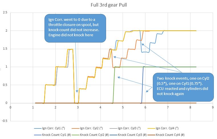
Here’s a normal 3rd gear pull with all 4 cylinder Ign Corrections and Knock Counts graphed. As you can see, ignition timing walks up when there is no knock in a step-wise fashion. When there is knock it drops down stopping further knock. If the knock events happened earlier in the pull or were of a higher intensity, Ign Correction could have become negative.
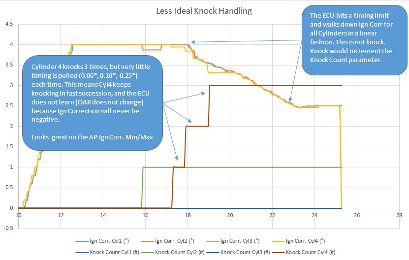
Here is how we can setup the same knock detection system in a less ideal manner. At first glance, it looks like this engine is basically not knocking at all. However if you look carefully, you can see that there were 4 knock events. The amount of timing pulled for each event is very little. This does two things. One, not enough timing is being pulled to stop the occurrence of further knock. Secondly, pulling so little timing will mean Ign Correction values will not be negative even though the engine could be knocking heavily and continuously. This in turn will mean the OAR will not adjust and the tune will not adapt to the fuel quality used.
For this reason, watching Min/Max Ign Correction on the AP can be very misleading. Not only does it not show you how many times the engine knocked, it also doesn’t show you how intense the knock was. To determine the performance of the tune, a full datalog is always necessary or at least a good understanding of HOW the tune handles knock events.

%20Pump.jpg)
.JPG "STRATIFIED X4tra Fuel System - EcoBoost 2.0L/2.3L")

 Once the motor is built and fuel system upgraded you can of course push higher with higher octane fuels.