How to perform a compression test on a Ford Focus ST

Compression tests are a very important tool in assessing your motor’s overall health. An especially convenient time to do this is when you are checking your car’s spark plugs. It’s also good to get a baseline compression test before adding parts or tuning the ST. A weak compression test result is something to be investigated further as it can be an indication of a mechanical failure (worn rings, poorly sealing valves, etc.)

On the Focus ST checking your compression is quite straightforward:

Step One – Prepare for testing:

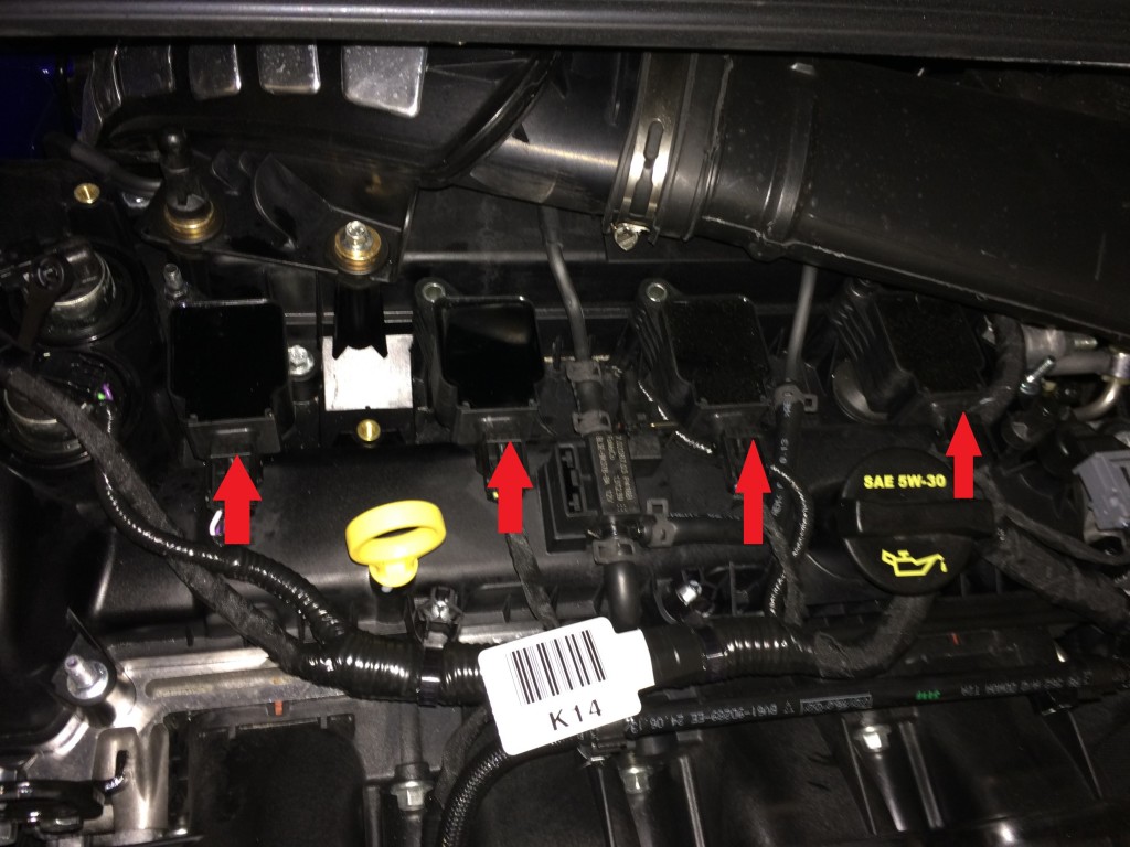
Preparing your Ford Focus ST for compression testing could not be any easier. First drive the car so that it is decently warm. Park it and carefully pull off the coil packs and remove all four spark plugs.

Step Two – Install the Compression Tester:

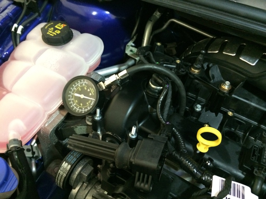
You can purchase a number of compression testers and they range in price and quality. Some of the very low quality ones can give poor or erratic readings. So if you get abnormal readings on an engine running well, then it is worth trying another tester. The compression tester simply screws into your spark plug hole. Make sure the O-ring makes contact with the cylinder head in order to prevent a false low compression reading.

Step Three – Test Your Compression:

To do this you simply push both the accelerator and the clutch all the way down. Once the clutch and accelerator are depressed press the start/stop button to begin the cranking process. Wait until you’ve heard about 15 cranks of the motor then press the start/stop button again to stop the process. Keeping the accelerator down the entire time prevents the injectors from firing while testing compression. If you have a friend helping; have them watch the gauge – ideally you want to crank until the needle stops moving up.

Make sure that you allow the same cranking duration for all four cylinders to allow for consistent readings.

Interpreting the Results:

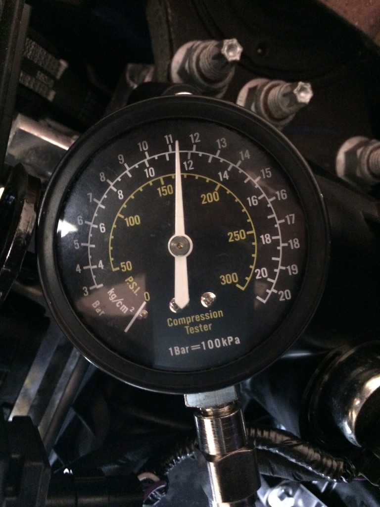
Compression numbers will vary slightly from motor to motor but for a healthy internally stock ST motor expect around 160-170 psi (~11 bar) at sea level on a mild day.

The altitude and internal engine changes (pistons, cams, etc.) will affect compression readings. With altitude, the higher you go in altitude the lower the compression will read and this is perfectly normal. Multiply sea level numbers by the table below corresponding to your altitude to get what you should expect if you are testing at higher altitudes. For example a healthy ST motor with 160psi compression at sea level will have a compression of (160*0.8617) around 138psi.

  • 1000′ = .9711
  • 2000′ = .9428
  • 3000′ = .9151
  • 4000′ = .8881
  • 5000′ = .8617
  • 6000′ = .8359
  • 7000′ = .8106
  • 8000′ = .7860

Another indicator of a healthy motor is that the compression is fairly even across all cylinders. The rule of thumb is that all cylinders should be within +/-10% of each other.

If you suspect there is a problem and repeated compression tests indicate this, you will likely have other running issues such as oil consumption, fouled plugs, misfiring, etc. The compression test can identify the problem cylinder and you can then investigate further. The next step would be a leakdown test to show you where the compression is escaping (past the rings or past the valves). This requires more equipment so the beauty of the compression test is that it is quick and inexpensive with minimal tools needed.

Record the readings in order and keep the records to track the health of the motor and catch any issues if they show up later down the road.

Happy Testing,

The Stratified Team

Spark Plug Tech

We here at Stratified are often asked what are the best plugs to run in our modified cars. The answer to this question depends largely on the primary use of the vehicle, and the extent to which it has been modified.

TL;DR: Buy your NGK LTR7IX-11 plugs on our website HERE.

When changing spark plugs in your vehicle there are two things to consider:

1. The spark plug gap:

This is the easier of the two considerations; for the Ford Ecoboost engine found in the Focus / Fiesta ST as well as the DISI in the Mazdaspeed vehicles we always recommend a plug gap of 0.025 – 0.026″. It is important that the plug be properly gapped or else the car will miss fire under boost/load. A larger gap produces a larger, hotter, spark which helps increase combustion efficiency, however, the larger the gap the harder it is for the ignition system to send a spark across the gap. This is especially evident in the Ecoboost and Mazdaspeed motors which run high boost levels and sparking resistance increases with increased cylinder pressure. Conversely, if the plug gap is too small then the spark created may be too small/weak to properly ignite the combustion mixture.

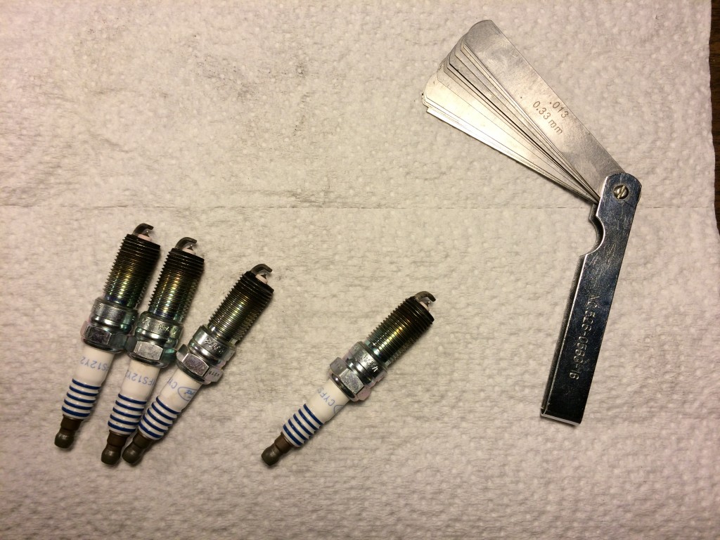
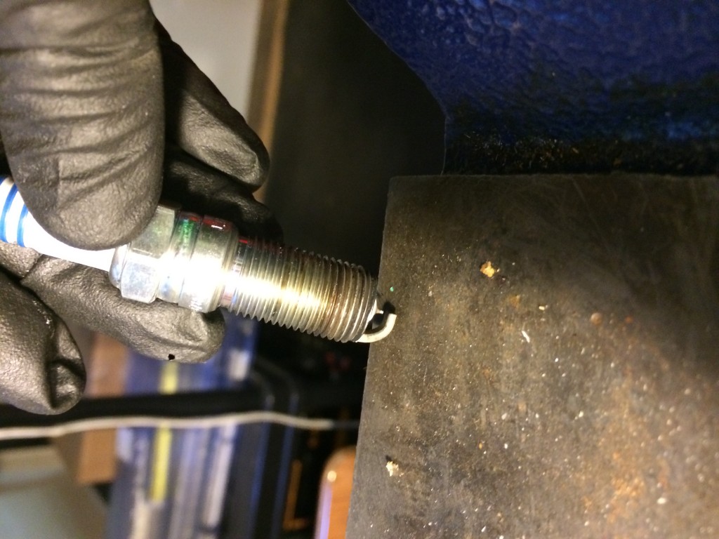
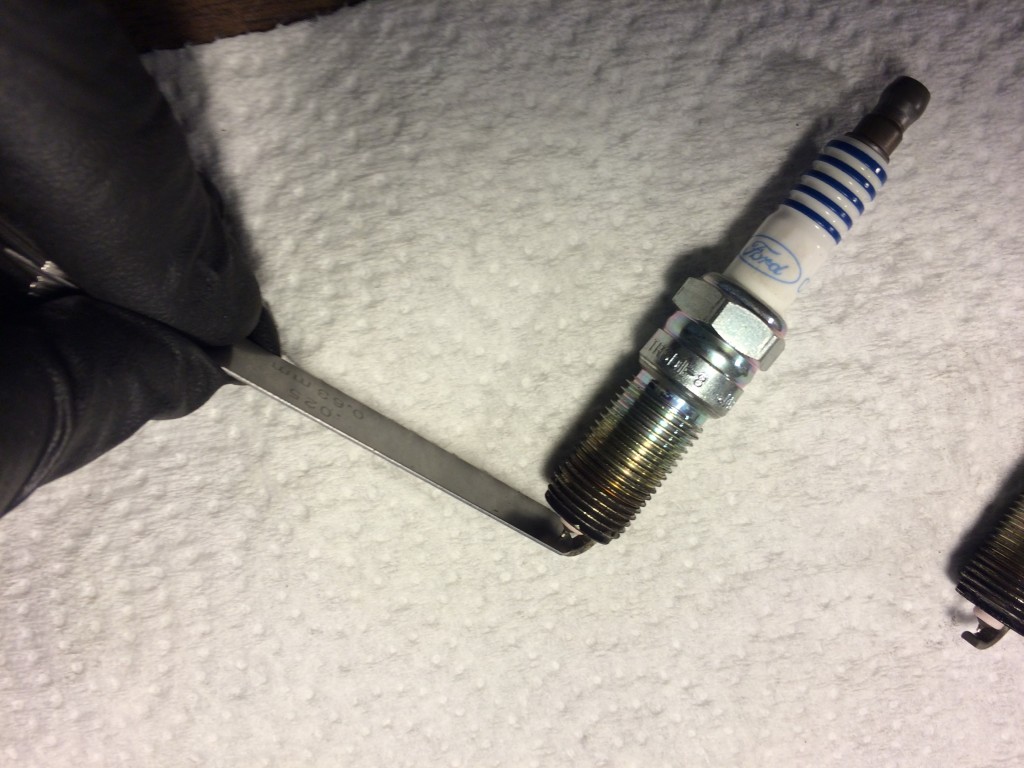
Most plugs for the Ford ST and Mazdaspeed vehicles come with a gap that is larger than our recommended 0.025 – 0.026″, thus it is necessary to lessen the plug gap. When checking your gap it is important to use proper feeler gauges; you’ll know you’re at the right gap when the feeler passes through the gap with minimal resistance. When closing your plug gap it is important that you do not push up against the plug’s centre electrode as it is easy to damage. The recommended gaping procedure is to tap the ground electrode against a hard surface such as a vice or sturdy shop table several times and then to recheck the gap. You will quickly get the hang of this.

The proper tool to measure your plug gap:

Tap the ground strap down gently checking the remaining gap often:

When the feeler gauge passes through without catching you know you’re at the right gap:

The spark plug gap will generally widen as the spark plug is used. This is due to the erosion of the ground strap but also due to the strap experiencing heating and cooling cycles. If you start to experience misfires and it’s not time for a plug change yet, pull the plugs out to check and re-adjust the gap as necessary.

2. The spark plug heat range:

This is where your modifications, and primary use of the vehicle come into play. Cold plugs are better for highly modified engines, while hotter plugs are more reliable on a daily driven vehicle. If you primarily use your vehicle for low speed daily driving or allow it to idle for extended periods of time, then a cold plug may foul. If you race your vehicle or repeatedly expose your engine to sustained high loads then a hot plug may cause pre-ignition which often results in a melted piston.

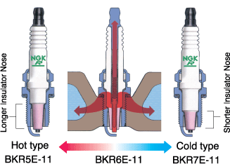
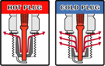
Now you may be wondering to yourself “What does the heat range even represent?” A common misconception is that a hotter plug produces a hotter spark; this is not true. The heat range boils down to how much heat the plug dissipates into the cylinder head. The pictures below provide a good representation of the spark plug heat range:

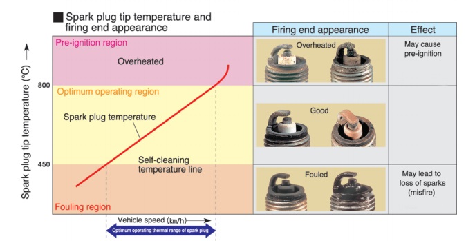
As you will notice, the hotter plug has a much longer portion of the insulator nose exposed to the combustion chamber. This longer nose goes hand in hand with a reduced surface area for the heat transfer. Since hotter plugs leave less area for this heat transfer to occur the firing end will get much hotter. This reduced heat transfer is necessary when your vehicle is driven slowly or often idled for long periods of time as it helps keep the spark plug at optimal operating temperature (which prevents fouling).  However, if the plug chosen is too hot then the insulator tip may become overheated during spirited driving. Once the insulator tip reaches temperatures of around 800C (1470F) it can (will) act as a pre-ignition source (think of a glow plug on diesels) lighting the mixture long before the ECU initiates the ignition event. Pre-ignition is the silent killer of engines; once it occurs there is no sound (knock sensor does not become triggered), there is no warning, only melted pistons/plugs. Due to advancements in engine design pre-ignition is not very common in modern street vehicles.

On the other hand, if the plug selected is too cold then the insulator will never be able to reach its self-cleaning temperature of around 450C (840F) and carbon deposits will start to accumulate on the insulator nose, leading to a fouled plug. Fouled plugs will misfire causing a loss in power and fuel economy. Furthermore, the built up carbon on a fouled plug could start to ember as insulator tip temperatures begin to rise during spirited driving (for example going to a track day, or a canyon run). This embering carbon build up is again an ideal pre-ignition heat source. As you can see going both too cold and too hot can be detrimental.

Another consideration with the heat ranges is cold starting. A plug that is of a colder heat range may have a harder time starting your vehicle when the temperatures start to drop.

Keep in mind that if you are having any doubts about your spark plug health it is possible to “read” your plugs. The appearance of the firing end can tell you a lot about your plug’s operating temperatures as well as the health of your engine. Below is a graphic showing what it is you need to look for. If you are running a colder than OEM plug and it is carbon fouled then you should return to the OEM heat range. If you manage to overheat a plug and haven’t killed your engine then we recommend going at least a step colder.

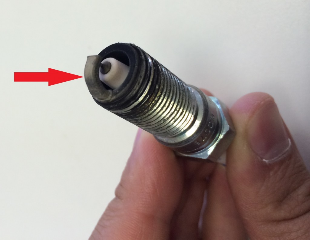
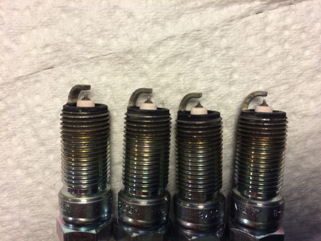
Another way to check whether the plug’s heat range is correct for your motor is to check the annealing point on the ground strap. If the heat range is correct the annealing line should be around the beginning of the ground strap bend. If the annealing is occurring too close to the electrode then you know that your plug is too cold. If the annealing occurs far down the ground strap bend then the plug is too hot. Here are a couple of pictures of some healthy OEM plugs with around 3,000 miles on them from the Stratified Focus ST development car that were replaced with a step colder plug along with the downpipe, intercooler, and intake (and some tuning of course!). Notice how the colour of the ground strap starts to change right at the beginning of the bend; looks like Ford did their homework!

In conclusion, too cold or too hot of a plug is detrimental. There is a misconception that a plug will cause knock and this is generally not the case. If a plug is to do long term damage, it is pre-ignition and that is not picked up by any knock sensor but also dangerous and thankfully, fairly rare on both the MazdaSpeed and Focus ST/Ecoboost platforms.

For the DISI motors we recommend running a spark plug that is one step colder than OEM. Generally the Mazdaspeed motors do not like running plugs that are two steps colder than OEM unless very heavily modified. Cars that are running higher compression, large amounts of boost, or are often tracked / driven aggressively for extended periods of time may at times require a plug that is two steps colder than OEM (for example have an extra set of colder plugs for track days).

For the Ford Ecoboost we still recommend a plug that is one step colder than OEM for mildy bolted cars especially since 21+psi of boost is quite common. For highly modified cars that see a lot of heat it is advisable to try a plug which is two steps colder than OEM. The Ecoboost motors seem to be able to manage colder plugs better than the Mazdaspeed motors.

For both the MazdaSpeed DISI and Ford EcoBoost the recommended plugs are either the NGK LTR7IX-11 or Denso ITV-22.

Remember to not forget to change the plugs when worn and to not overtorque them when installing.

Happy Tuning,

The Stratified Team
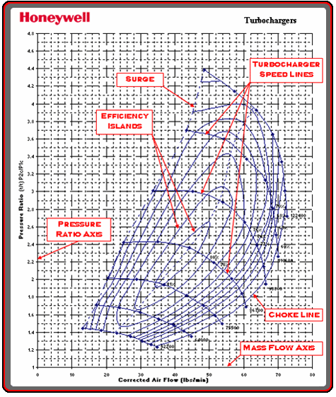
Photo Credits:

Heat Ranges and plug conditions – NGK TECH 

Hot Vs Cold Plugs – Hot’N’Cold


COBB Accessport V3 with Stratified S-OTS+ Tune for Focus ST


Ford Focus ST Plus Stratified S-OTS+

We are excited to announce that Stratified Automotive is now selling the COBB Accessport V3 packaged with a Stratified S-OTS+ tune modified to maximize your vehicles performance and driveability.

The COBB AP V3 is by far the best tool available to increase the torque, horsepower, and response of your Ford Focus ST. However, as powerful as this tuning tool is, it can be very easy to become overwhelmed when attempting to tune your own vehicle. This is why we created the Stratified S-OTS+ maps which take advantage of our years of experience and engineering background to offer you the easiest, most sophisticated, tuning package on the market.

The Stratified S-OTS+ maps for the Focus ST are modified to accommodate for different types of gasoline fuels available in your area (91 or 93 octane), different launch control settings, flat foot shifting, and we can even include a low boost tune for winter driving or if high quality fuel is not available. Switching between tunes (for different flat foot or launch control settings, and high/low boost map) is extremely easy thanks to the COBB Accessport’s map switching feature (see the youtube link below).

Follow the link below to take advantage of this offer and get your first taste of being Stratified Tuned!

COBB AP V3 and S-OTS+ Package


A Technical Discussion of Intakes and Turbocharging

I see a good amount of intake discussions popping up on forums and wanted to do a small write-up about what to look for when choosing an intake and some turbocharger and airflow theory.

The rule of thumb with intakes is that the larger the diameter, the shorter the intake and the fewer the turns the better in terms of what the turbo “likes” (less losses = more power).  Let’s elaborate on this a little bit.

Turbocharger compressors (the silver cold side of the turbo) operate at what is called a pressure ratio. What this means is that the compressor increases the pressure of the air from the Inlet (from intake) to the Outlet (to intercooler) of the compressor when they are spun up by the exhaust gases (spooled up). This gives us BOOST!

Boost gives the engine more airflow than it can draw through itself (essentially increasing the volumetric efficiency) allowing it to make more power. The amount of airflow needed is defined by the size and volumetric efficiency of the engine and the power requirements. We’ll go into more detail on this in another write-up.

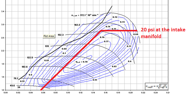
Turbocharger compressor performance is illustrated by a compressor map. A sample compressor map is shown below with the features highlighted. You can read more about compressor maps in this excellent series by Garrett/Honeywell:

Now, the size of the compressor and turbo really depends on application. Generally, we want very little lag and decent top end so the turbo we choose (and the stock one in most cars especially) is driven very hard. In such a case, the lower this compressor pressure ratio, the more efficiently the turbo works and the less “work” the exhaust has to put into the turbine to make it spin.

This reduces pumping losses (increases volumetric efficiency), reduces heat, and allows denser air to reach the motor while increasing the knock threshold. All good things and this applies to ANY turbo unless it is grossly oversized for the engine in which case there are bigger problems to address.

How is this related to intake and boost we measure at the manifold?

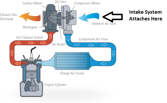
You can imagine air follows this path into the motor:

Air Filter → Intake Tubing/MAF Sensor → Compressor Inlet → Compressor Outlet → Hotside Tubing → Intercooler → Cold Side Tubine → Throttle Body → Intake Manifold → Intake Valves/Head → Exhaust Valves/Head → Turbo Turbine → Downpipe → Rest of exhaust.

The image below shows this using an illustration.

The compressor map shows you how much a turbo flows at a given pressure ratio (pressure difference between compressor inlet and outlet) at a standard temperature.

The airflow is on the horizontal (x axis) and the pressure ratio is on the vertical (y axis). As the RPMs increase the motor requires more air to produce more power. For simplicity, let’s say we are running 20 psi of boost at the manifold. You can plot out where the motor operates on the compressor map based on how much air it consumes at that 20 psi with that particular turbo (this case a K03). This looks something like this when the engine is doing a pull in a single gear.

Notice how in this case the pressure ratio that the turbo is operating at is around 2.8 on the vertical axis. At sea level this translates into 26 psi of boost pressure the compressor must generate. But I just said that the car is operating at 20 psi of boost at the manifold right? How can this be?

When you draw air from outside, you are drawing air in at atmospheric pressure. However when it gets pulled through the filter and air tubing, the pressure actually drops BELOW atmospheric. This is due to something called the Bernoulli Principle.

The turbo then pushes air through to the motor but across all the other intake tubing and intercooler you lose more pressure due to the same principle until it reaches the manifold.

When you measure boost at the intake manifold you are measuring it against the atmospheric pressure (called Gauge Pressure) but your compressor is actually operating at a higher pressure ratio/boost level.

Let’s use an example:
– Say the manifold pressure is 20 psi as measured by the ECU or a boost gauge.
– The pressure drop from the intercooler and the piping AFTER the turbo is 4 psi (for example).
– The pressure drop from the intake and filter BEFORE the turbo is another 2 psi (again an example).

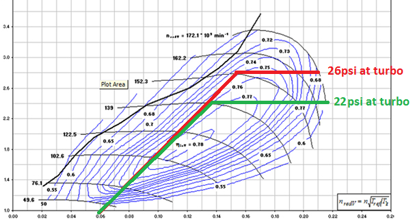
That means that the compressor is actually pressurizing air to 26 psi to get you 20 psi of manifold pressure. The more you reduce this pressure drop in front of and after the turbo, the slower you need to spin the turbo, the more efficiency you’ll gain, and in the case of undersized turbos like the OEM, you will gain airflow all while keeping your 20 psi at the manifold.

All this means to you is that your car will be faster! The diagram below shows the same compressor map with the same 20 psi of boost at the manifold (and 26 psi at the turbo in red). Now, let’s assume we run a more efficient intercooler and bigger and more efficient intake and these only drop pressure 1 psi each. This changes the pressure ratio at the turbo to 22 psi to get the same 20 psi at the intake manifold! This is shown in green.

What can we conclude about running a turbo along the green line? Thankfully all good things about both power and reliability.

– Turbo spends more time in the higher efficiency islands.
– The green line extends further meaning that the turbo will flow more air without over-spinning.
– The turbo spins slower, reduces exhaust back-pressure, increases overall engine efficiency
– Turbo runs cooler at lower pressures.
– Engine is less likely to knock.
– Turbo life is extended.

How is this related to the intake?

Larger diameter intakes that are shorter, have less turns, and a better flowing filter will really help here. Believe it or not even the filter makes a measurable difference when you’re working with a maxed out turbo like what is installed on most OEM cars and most medium sized turbos. Of course the intake must also fit in the engine bay and also importantly shield the incoming air from heat without being restrictive.

OEM components are sized for the power requirements of the stock car and noise constraints but often do a great job shielding from heat. Compare the sizes, locations, and design of OEM and aftermarket intakes to see this. Some aftermarket intakes are definitely better designed than others.

The intercooler and piping after the turbo have a similar effect and should follow the same low restriction, high efficiency principle. There are a few more details to charge air cooling that will be covered in a different article.

These are some of the things to think about when choosing an intake for the MazdaSpeed, Focus ST, or any other turbocharged car!

Happy Turbocharging!
Alex@Stratified

Image Credits:
http://www.cap-ny153.org/forcesthrust.htm
http://blog.perrinperformance.com/alta-billet-56-turbo-upgrade/
http://http://www.audizine.com

The implications of a blown boost pressure line

This is a scenario I have seen a few times and I think it is worth going through and the implications of blowing the pressure signal hose off your wastegate or EBCS.

First of all, this is a very dangerous scenario. In most cases a single event like this will either damage or blow the OEM motor. The most dangerous part of this is that it is UNCONTROLLED and pressures rise much too quickly. This is why we have created our Guardian Angel. It is great insurance for this scenario.

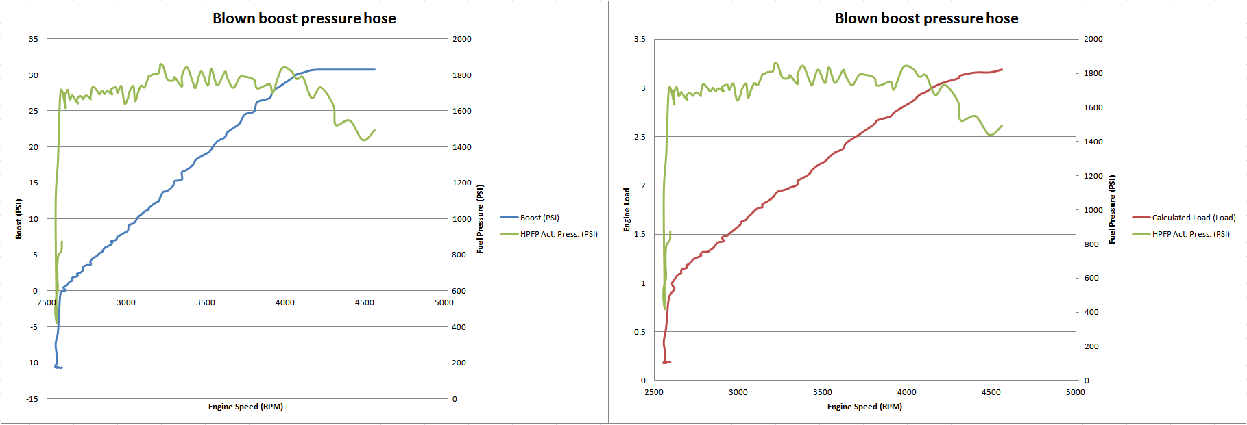
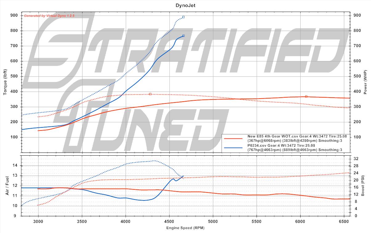
Below is the event shown graphically. This is a car running a GTX3071 with a 3 port COBB solenoid and the hose blew off the solenoid barb. The barbs are really small on these solenoids – this is why we went with 1/4″ barbs on our 3 Port. Better to struggle pushing the hose on than have it blow off or leak.. The same thing would happen if the hose blew off the wastegate port.

You will see boost rising in the left hand graph until it pegs the 3 Bar MAP sensor and it continues rising past this. The boost cut in this car is set at 25psi and you can see that it took over 1000 RPM of being above 25psi in 4th gear for the ECU to cut.

During this time, load (airflow) continued increasing and you can see this in the left hand graph exceeding 3.0 load by 4100 RPM and exceeding 100% injector duty by 4400 RPM. At the point where 100% injector duty was reached the limits of the Autotech internals (or perhaps in-tank pump) are also reached and fuel pressure starts to dip before the ECU initiates the cut.

This is a harsh way to see just how much airflow the GTX3071 can generate (a lot!) as well as where the limits of the fuel system lie in the low end. Thankfully, he was on E85 and the engine stayed together this time but it’s not certain if anything was tweaked internally. I estimate boost exceeded 35psi before the ECU cut based on extrapolating past where the sensor was no longer able to read.

What does this look like on Vdyno next to a controlled 4th gear pull? Yes, there probably was some wheel spin but you get the idea.

To avoid this there are several important steps:
1. Use proper hose clamps and not zap straps (zip-ties) around hoses. Zap straps will either not apply enough pressure or melt and beak in high heat areas.
2. If the barbs are mismatched in size, either get an adapter or different barbs, or a solenoid with properly sized barbs.
3. If you are altering the hoses or boost control system in any way from OEM, the Guardian Angel is highly recommended. It is very cheap compared to a blown motor due to a single mishap. It protects you from mechanical as well as tuning errors.